- 您现在的位置:买卖IC网 > Sheet目录3753 > ATMEGA169P-16MCHR (Atmel)MCU AVR 16KB FLASH 16MHZ 64-VQFN
35
8018P–AVR–08/10
ATmega169P
The capacitance (Ce + Ci) needed at each TOSC pin can be calculated by using:
where
Ce - is optional external capacitors as described in Figure 8-2 on page 33.
Ci - is is the pin capacitance in Table 8-8.
CL - is the load capacitance for a 32.768 kHz crystal specified by the crystal vendor.
C
S - is the total stray capacitance for one TOSC pin.
Crystals specifying load capacitance (CL) higher than the ones given in the Table 8-8, require
external capacitors applied as described in Figure 8-2 on page 33.
The Low-frequency Crystal Oscillator must be selected by setting the CKSEL Fuses to “0110” or
“0111” as shown in Table 8-10. Start-up times are determined by the SUT Fuses as shown in
Note:
1. This option should only be used if frequency stability at start-up is not important for the
application
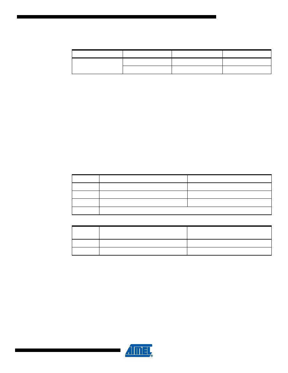
Table 8-8.
Capacitance for Low-Frequency Crystal Oscillator
Device
32 kHz Osc. Type
Cap (Xtal1/Tosc1)
Cap (Xtal2/Tosc2)
ATmega169P
System Osc.
16 pF
6 pF
Timer Osc.
16 pF
6 pF
Table 8-9.
Start-up Times for the Low-frequency Crystal Oscillator Clock Selection
SUT1..0
Additional Delay from Reset (V
CC = 5.0V)
Recommended Usage
00
14 CK
Fast rising power or BOD enabled
01
14 CK + 4 ms
Slowly rising power
10
14 CK + 65 ms
Stable frequency at start-up
11
Reserved
Table 8-10.
Start-up Times for the Low-frequency Crystal Oscillator Clock Selection
CKSEL3..0
Start-up Time from
Power-down and Power-save
Recommended Usage
0110(1)
1K CK
0111
32K CK
Stable frequency at start-up
Ce Ci
+
2
CL
Cs
–
=
发布紧急采购,3分钟左右您将得到回复。
相关PDF资料
2-1546217-0
TERM BLK RCPT 20POS SIDE 5.08MM
1-1546217-9
TERM BLK RCPT 19POS SIDE 5.08MM
1-1546217-8
TERM BLK RCPT 18POS SIDE 5.08MM
1-1546217-7
TERM BLK RCPT 17POS SIDE 5.08MM
1-1546217-6
TERM BLK RCPT 16POS SIDE 5.08MM
1-1546217-5
TERM BLK RCPT 15POS SIDE 5.08MM
1-1546217-4
TERM BLK RCPT 14POS SIDE 5.08MM
1-1546217-3
TERM BLK RCPT 13POS SIDE 5.08MM
相关代理商/技术参数
ATMEGA169P-16MCU
功能描述:8位微控制器 -MCU AVR 16KB, 512B EE 16MHz 1KB SRAM, 5V
RoHS:否 制造商:Silicon Labs 核心:8051 处理器系列:C8051F39x 数据总线宽度:8 bit 最大时钟频率:50 MHz 程序存储器大小:16 KB 数据 RAM 大小:1 KB 片上 ADC:Yes 工作电源电压:1.8 V to 3.6 V 工作温度范围:- 40 C to + 105 C 封装 / 箱体:QFN-20 安装风格:SMD/SMT
ATMEGA169P-16MU
功能描述:8位微控制器 -MCU AVR 16K FLASH 512B EE 1K SRAM LCD ADC RoHS:否 制造商:Silicon Labs 核心:8051 处理器系列:C8051F39x 数据总线宽度:8 bit 最大时钟频率:50 MHz 程序存储器大小:16 KB 数据 RAM 大小:1 KB 片上 ADC:Yes 工作电源电压:1.8 V to 3.6 V 工作温度范围:- 40 C to + 105 C 封装 / 箱体:QFN-20 安装风格:SMD/SMT
ATMEGA169P-16MU SL383
制造商:Atmel Corporation 功能描述:MCU 8BIT ATMEGA RISC 16KB FLASH 3.3V/5V 64PIN MLF - Tape and Reel
ATMEGA169P-16MUR
功能描述:8位微控制器 -MCU AVR LCD 16KB FLSH EE 512B 1KB SRAM-16MHZ RoHS:否 制造商:Silicon Labs 核心:8051 处理器系列:C8051F39x 数据总线宽度:8 bit 最大时钟频率:50 MHz 程序存储器大小:16 KB 数据 RAM 大小:1 KB 片上 ADC:Yes 工作电源电压:1.8 V to 3.6 V 工作温度范围:- 40 C to + 105 C 封装 / 箱体:QFN-20 安装风格:SMD/SMT
ATMEGA169P-8AU
制造商:ATMEL 制造商全称:ATMEL Corporation 功能描述:Microcontroller with 16K Bytes In-System Programmable Flash
ATMEGA169P-8MU
制造商:ATMEL 制造商全称:ATMEL Corporation 功能描述:Microcontroller with 16K Bytes In-System Programmable Flash
ATMEGA169PA
制造商:ATMEL 制造商全称:ATMEL Corporation 功能描述:8-bit Microcontroller with 16K Bytes In-System Programmable Flash
ATMEGA169PA_1
制造商:ATMEL 制造商全称:ATMEL Corporation 功能描述:High Endurance Non-volatile Memory segments